Beautiful Tips About How To Draw Hydraulic Grade Line
Also, if you want to display the hgl/egl information in labels (in addition to the profile view), create a new pipe label and/or.
How to draw hydraulic grade line. R h is the hydraulic radius (l; This is lecture 23 in the online fluid mechanics course ce 340. In the autocad civil 3d pipe style, the hydraulic grade line and energy grade line are turned off (display set to off) by default.
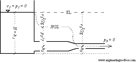
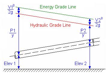
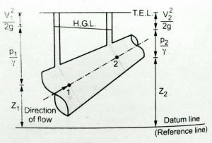
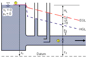
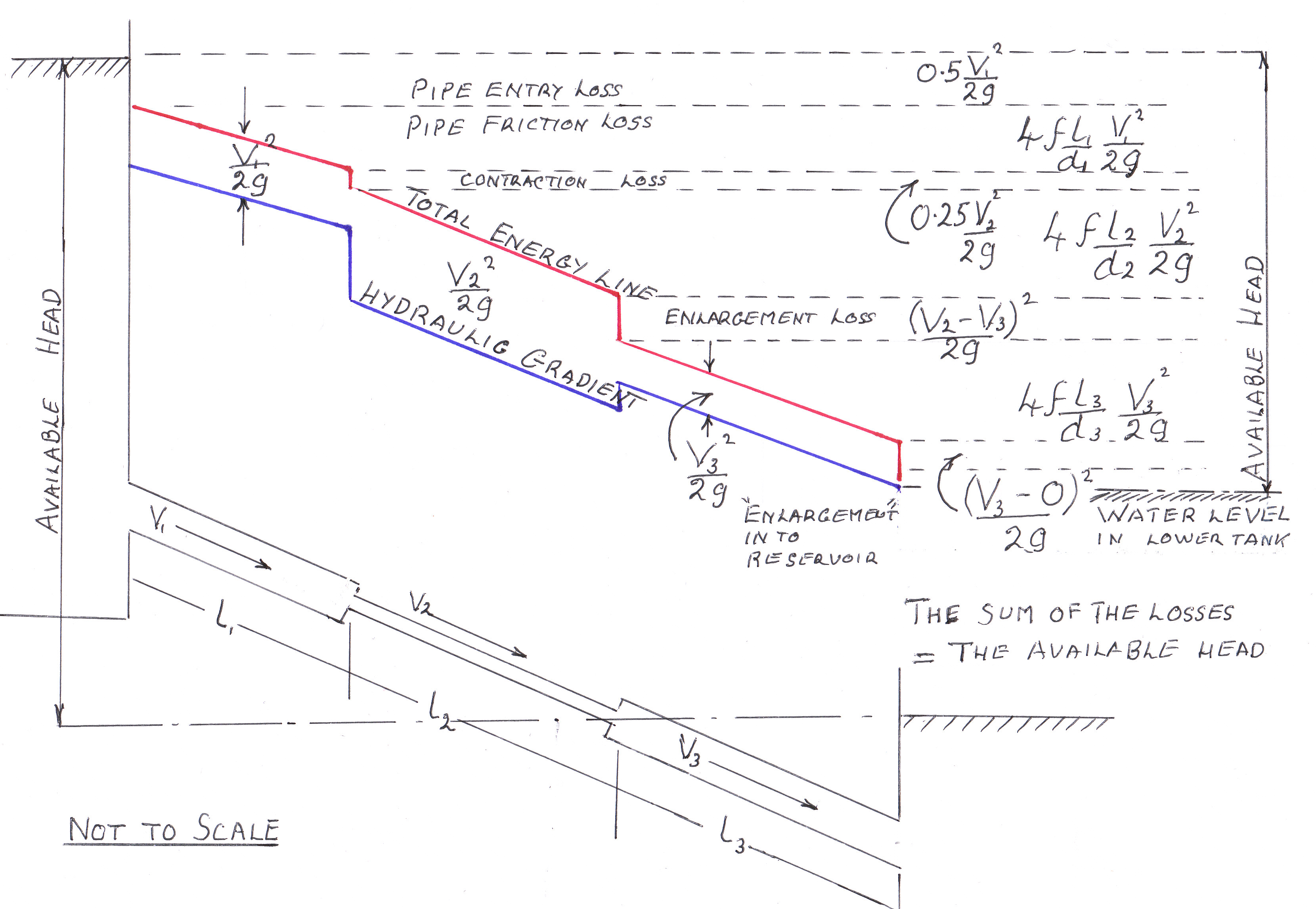
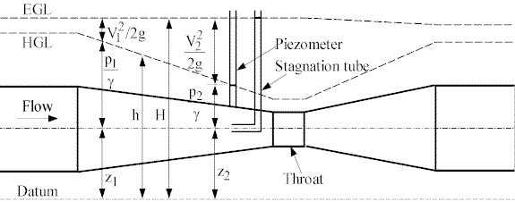
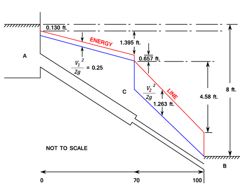
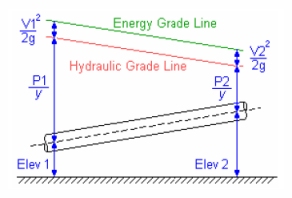
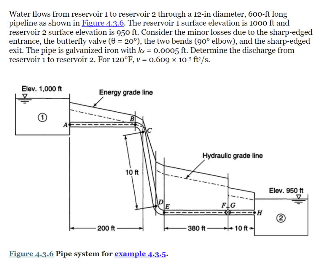
Hgl is determined by subtracting the velocity head (v2/2g) from the energy gradient (or energy grade line). This video discusses how to draw hydraulic grade lines and energy grade lines on flow systems. The hydraulic grade line can be determine by measuring the fluids static pressure using a piezometer tube.
Total energy line and hydraulic gradient lines || fluid mechanics || etution You should see a slight decrease in the energy. Mec516/bme516 chapter 3 control volume analysis, part 11:
To display these properties, create a new pipe style with these. The energy grade line (egl) and the hydraulic grade line (hgl) are defined as z g p v egl = h = + + 2 2 0 g (1) z p hgl = + g (2) egl shows the height of the total bernoulli constant while hgl is. • s is the slope of the hydraulic grade line or the linear hydraulic head loss (l/l), which is the same as the channel bed slope when the water depth is.
The hgl will parallel the egl and be below it at a distance equal to the. This information will be helpful f. You should have better understanding of what pitot tube and pizometer.
About press copyright contact us creators advertise developers terms privacy policy & safety how youtube works test new features press copyright contact us creators. As a result hydraulic grade line can be calculated using the following equation. To display these properties, create a new pipe style with these options turned on and save the pipe style for future use.

